
Client tutorial
This document is intended as a tutorial for the new Network Intelligence user. Some familiarity with the client user manual is assumed. The tutorial covers setting up a simple network representation from imported routers, and subsequent viewing of traffic flows across the created network. All it requires is the user to connect to the server at gadgets.co.nz on port 6700 using the Network Intelligence client software.
|
Connecting to the tutorial server Building a network Moving around the environment Viewing different traffic |
Connecting
Begin by starting up the Network Intelligence client. We are going to connect to the server located at Gadgets Software, so we need to configure a suitable usercode and password. Open the configuration->userdetails... window and enter demo for the usercode and demo for the password. The demo user has been set up on this server to have administration privileges and with this user you will have the rights to create a network, as opposed to just viewing one.
In order to connect to the Gadgets server go to the open connection window connection->open... and enter gadgets.co.nz for the host address and 6700 for the TCP port number. Now go ahead and connect to the server.
Building
The three dimensional environment window will open, and what you see will depend on what has already been constructed. The area may be empty, or it may be littered with someone elses network. Remember that anyone running the client software is allowed to connect to this server, and it's possible they left the network in a mess.
We will begin by clearing out the network if one exists. We will do this by selecting action->delete->delete routers.... Select all the routers in the list. An easy way to do this is to select a range by left clicking on the top item, then shift clicking on the bottom item. Click delete and pretty much everything should disappear. Don't worry if there are a few Autonomous Systems (ASes) left floating in the sky.
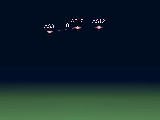
Now begin constructing the network. In a typical setup, all the configuration files for all the routers in a network would be placed in a config directory. You can load these routers into Network Intelligence with the action->add/edit->router (import)... menu option. As with the delete option, you will be presented with a list of routers. This time it's a list of all routers in the config directory.
Select all of the routers, and click add. All of the routers will be loaded, and they will all appear at the origin location (0,0,0).
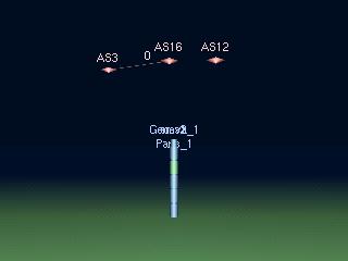
Having numerous routers occupying the same space looks quite messy, so we will move each one apart so they are nicely spaced on the screen. To do this, first select all of the routers using the action->select... option. All the routers will turn yellow to indicate they are selected. Next, use the action->auto arrange... option to place the routers evenly in the window.
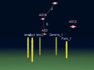
Next we are going to automatically generate the circuits that connect the routers together. This is quite easy to do as Network Intelligence uses the interface details to figure out which interfaces are connected together.
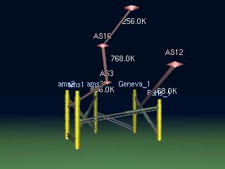
With all of the routers still selected (still yellow in colour), select the action->connection discovery option and you will see all the circuits connecting all the routers automatically put in place. You may also see some network traffic, flowing down the newly created circuits. You now have a complete network as specified by the router configuration files!
Moving
In this part of the tutorial we will cover moving around within the three dimensional environment.
Begin by clicking and holding the RMB while the cursor is over the ground or the sky. Move the mouse forward slightly and you will find you move forward in the environment. As you drift towards one of the routers, move the mouse from side to side in order to keep track of a router until you a right in front of it. Release the RMB and you will stop moving. This movement allows you to translate yourself anywhere in the horizontal plane while keeping the same heading.
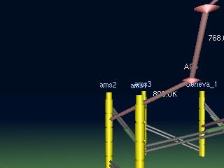
Now using the LMB click and hold the button down while the mouse pointer is positioned on the top of a router. Move the mouse to one side and you will rotate around the router. If you pull the mouse back, you will move further away from the router as you turn. Release the LMB to stop. This movement is similar to orbiting around an object with your heading also changing.
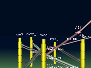
Now click and hold the LMB while the mouse pointer is over empty space. By moving the mouse from side to side, as well as forwards and backwards, you will be able to look around the environment. This allows you to look up, down, and side to side.
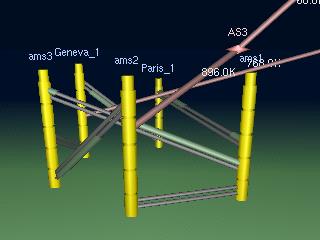
Unselect any selected objects by clicking (CTRL-LMB) on the background or empty sky.
Viewing
As the default, we are viewing all traffic flowing across the network. This will be visible as packets flowing down the circuits connecting routers, as well as flows leading off to the autonomous systems in the sky. The loading on a router to router circuit is represented by the length of the packets travelling down the circuit. A circuit that is entirely covered by a packet is saturated while circuits with very short packets are very lightly loaded. Flows off the network are represented differently. The size of the flow is labelled along side. The size of the "pipe" represents the flow size relative to other flows out of the network. In this way it's quite easy to pick the largest and hence most significant flows.
We can also see the loading on each of the in-network circuits. None of them are particularly full, so the network is operating below full capacity. Any over-utilised links will, in addition to having packets completely covering the circuit, will also turn red. This helps with identification.
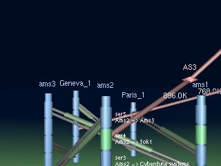
In some cases we wish to look at the traffic coming from a particular connected network, perhaps a customer. For example we wish to see what sort of traffic they are generating so we can charge them accordingly. Network Intelligence lets us select a particular interface of interest. For this to work it is necessary for the interface to be gathering Netflow Exports. Such an interface will appear green instead of blue.
For this example we are going to look at traffic coming in router ams2 on interface ser4. This interface is gathering Netflow Exports and therfore appears green. Select the interface with a CTRL-LMB click on the actual interface.
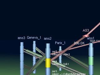
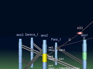
Select action->view->single interface traffic and the view will change to show all traffic coming in ams2/ser4. The main window will also update to show what traffic we are viewing.
In this case we see that actually no traffic is coming in the am2/ser4 interface at all!
This concludes the introductory tutorial. It is hoped this allowed you to become familiar with navigation within the environment as well as the process of building a network representation. Many of the menu options rely on these simple skills and you are now encouraged to experiment with the options available to you.
© Gadgets Software 2001-2008